Cabinets & Gate

This morning I made it over to Sundeleaf Painting in Milwaukie to pick up my cabinets. They look and feel awesome! The plywood edge layers are still visible for that authentic, hand-made retro aesthetic.

Master Craftsman Eric White says the process involves an undercoat, followed by two coats of “conversion varnish.” This is a special paint mixed on-site that includes the pigment, the varnish and a catalyst. This job took about 22 hours of labor and cost $900.

We left two top surfaces unfinished, so that my retro laminate will adhere to the raw maple plywood. The main piece is the countertop, of course. The piece you can see with the rounded corners is the bottom of the dinette table. (Yep, the bottoms and backs are all finished for weather-proofing goodness.) It will also get some chrome edging once I router the slot and apply the laminate. I also have some rounded chrome corners made by Fender, to attach to the sharp corners on the berth bases. Those will prevent any bloody shins.

I can’t reassemble the woodwork just yet. I need to finish the wiring, the insulation and the galley plumbing first. So I might just keep the cabinets in my SUV for safe-keeping.

When I arrived home, the RETROpad’s front gate had magically appeared. I just need to ramp some crushed granite gravel up against the entrance now. And as you can see, the slab is still not cured enough to park on.

Not taking any chances… Patience…

Illumination

Today was another full, sunny day of RETROvan work, taking advantage of dry, albeit chilly fall weather. I spent most of it rewiring some circuits and replacing the bad Ancor grommets with my good ones. No easy task, considering you have to disconnect and pull cables to do it.

I got all the aft LED lights secured with #4 1/2” screws and popped their chrome trim rings in place. And boy, they look beautiful!

I moved the two Fan-tastic Vent circuits off the Rover’s direct-connect load terminals and onto a dedicated circuit on the DC panel in the helm. So now they show up on the DC Ammeter as a dynamic load, moving the needle up and down as their thermostats reacts. Very cool. Literally.

So now that needle will reflect all DC loads including the vents, lights, entertainment system and gadget chargers.

I got the T3 cavity insulated and the panel installed. The T2 cavity is next. It’s directly between the helm and the galley cabinets, so it’s got a big concentration of electrical cables running through it — plus the TV mount which will need piecemeal insulation above it. The T1 (forward) cavity will be easier, but its insulation must be cut in a trapezoidal shape and I’ll have to dodge the aluminum angle brackets my Dad and I added up there to strengthen the roof over the cockpit.

I also made more of my AppRadio’s connections permanent since the left front speaker was crackling every time I moved the wires. For that I used 16 AWG spade connectors which can be unplugged at will.

I didn’t make it over to the paint shop today to pick up my my cabinets, but I’ll do that tomorrow while it rains. They did tell me the final cost: $900. Fine with me!

And finally, the RETROpad concrete is still a bit gray, so I’m going to wait another few days. Not happy that didn’t get poured while there was still some summer heat. But oh well. Gary said it’ll be stronger if it cures slower.

Insulation & Wiring Up Top

The RETROpad concrete hasn’t quite cured enough to park on yet, but today was a full, sunny day of RETROvan work. Yep, it’s Sunday but our teams both have byes (Dallas and Seattle).

This R-Max rigid foam insulation is pretty easy to work with. It was an excellent choice and should be well worth the trouble and expense (over $30 per sheet). The only problem is, to get clean cuts I have to use a jigsaw. And that means measuring and marking both sides because the blade only goes about half way through the 2-inch material. Here’s one of the vent garnishes, which I used as a template.

I ran new 16 AWG speaker wire for the rear ceiling panel (T7). That cable runs through four holes in each top corner cavity, exploiting the holes in the steel braces my Dad and I added, and converging over the cockpit where the Pioneer AppRadio receiver is. You can see how the aft vent, the HDTV antenna, and the aft lighting bank’s bus bar fit into the insulation. All of the electrical cables rest under the insulation and on top of the aluminum. That keeps them away from the more extreme heat of the sheet metal hull.

And here’s the ceiling with four cavities now complete, thanks to Olivia’s help. The vent trim is screwed back on, and the six LED lights are connected and snapped in. They also take three tiny screws each, to keep them tight against the panels. But I’ll have to make a trip to Home Depot for those tomorrow before I can snap the chrome trim rings on.

This is going to look amazing with all the reflections, especially when it’s polished up. I’m glad I never pulled the trigger on ceiling tiles or powder coating.

It’s sunny again tomorrow (Monday) so my plan is to finish the ceiling insulation, wiring and panels. That will be a major milestone. And hopefully the concrete will be mostly white by then, so we can finally moor the RETROvan on the RETROpad for some good old-fashioned RETROfun. 🙂

Switches, URL & Insulation

Today I cut in a few switches and sockets in panels D3 and P1. (D for Driver side, P for Passenger side; numbered fore to aft).

The first step is measuring, scribing and re-measuring, including a 1/16″ tolerance on all sides of the switch’s recessed body. The next step is drilling some 3/8″ corner holes to allow the blade to enter. The tape protects the aluminum from scratches caused by any gritty shavings under the jigsaw’s shoe.

These JR Products dimmer switches stupidly require a notch for the wiring. A better design would have the wiring come straight out the back. I haven’t wired the switches up yet because they were supposed to be white but they’re actually beige, and don’t match the other white trim. So I’m replacing them with black ones.

Here’s the result, with the face plate snapped in place and two Blue Sea Systems sockets mounted below, in 1-1/8″ holes cut with a hole saw. The top socket is dual USB ports. The bottom socket is a standard 12V cigarette-lighter type, which can be used for a variety of auto accessories. These fixtures aren’t wired yet. I’m waiting to remove that wall panel and insulate the cavity before connecting these cables and sealing the window up tight.

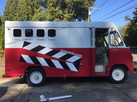
Today was sunny and dry, so I installed the last branding elements on both sides. This “scenario.org” die-cut text is 36 inches long. Signs Now produced it (after some ridiculous communication problems), but I found their vinyl to be inferior to the stripes I bought from VViViD up in Canada. It’s thinner and doesn’t have any air-release capability, so the slightest air bubble is impossible to remove and when you hit it with a heat gun it just melts and deforms. Not impressed.

And lastly today, I cut some rigid foam insulation and Velcro’d it up in to the T7 cavity. I had planned to use a 2″ thick piece on top and a matching 1″ piece on bottom, but there’s only room for another 1/2″ piece and I don’t think it’s worth the trouble. Two inches yields R-13.1, so that’ll have to do for the roof. The 1/2″ gap will accommodate various cables nicely. In the case of panel T7, that means the two aft speaker cables, which I’ll run tomorrow.And by the way, my new dehumidifier appears to be working! It has a 22-ounce reservoir for extracted water, and it was about 25% full by noon today. I had inspected the ceiling cavities by hand at about 9 AM and they were all condensation-free except for the area closest to the forward vent — which was the coldest, least-insulated area.

So my plan for Sunday is to insulate the entire ceiling so I can finalize the wiring up there and re-install the ceiling panels. I’ll keep the space heater and dehumidifier running and keep my fingers crossed that there are no actual leaks in the roof.

The Paint Shop

Eric at Sundeleaf Painting in Milwaukie (no, Oregon) sent me some great action shots of my cabinetry being professionally finished.

He says the pieces look really nice, and I agree. “Super smooth, low sheen.” They should look dynamite when everything’s installed. These colors are neutral on purpose, to make the RETROvan’s red accents and colored lights pop and reflect off the metal. There will be no visible wood tones when everything’s done.

Eric says this charcoal color looks dark in the photos, especially when wet. It’s called Wrought Iron from Benjamin Moore.

The last photo looks perfect to me, so these pieces must be drier. The hard, durable top coat also seals the maple plywood on all sides to make it weather- and mold-resistant.

Electric Jellyfish

Yesterday I wired up the forward bank of lights on the same circuit, but on its own dimmer switch.

They look like a pod of electric jellyfish. Our mail carrier stopped by and said, “Wow, it looks like some kind of party bus.” I told her, “Well yeah, you know, it’s always happy hour somewhere!”

I also got word that my cabinets will be finished today, but they need to sit in the shop a while in order to “off-gas.” So I’ll pick them up from Sundeleaf Painting on Monday. Eric promises to send photos.

Today I plan to remove the rest of the ceiling panels and work on the wiring near the helm, and maybe test-fit some insulation. I’ll need to remove the motorized TV mount too, then figure out where all the wall mounted accessories will go. That includes the light switch, the Rover solar charger/controller, the TV jack, the power strip, the Apple TV and the Apple Airport Extreme.

To make this safe and tidy, I ordered a couple of cable pass-throughs for panel P1. This one will go right below the Rover to channel its red and black solar and battery cables, which are 8 AWG (thick).

And this is a black 12-inch grommet made for a mail slot. That will go in the lower section of panel P1 to feed about a dozen cables between the wall cavity and the helm. The helm might get one of these as well. Right now I’m using about ten 3/4″ holes drilled through the plastic, which are hidden from view.

Yesterday it rained pretty hard and I notice the ceiling was wet. This may explain the RETROvan’s insidious “leaks.” But it looks like it’s just condensation, collecting on the roof and finding a place to drip, thereby impersonating a leak. This makes sense when the relative humidity tops 80% or 90%. It turns out this is a common problem with RVs here in the Pacific Northwest.

After some research, I’m going to try running my PuraFlame LED space heater 24/7 on low heat to dry out the air. Just enough to keep the interior above the dew point. That may do the trick. We’ll have more thunderstorms today, so I’ll keep an eye on it.

I also ordered a $35 dehumidifier, made by Ivation. I don’t have high expectations for this but it’s stylish and small. If it works, I’ll drill a hole and fit a drainage tube to its collection tray so I don’t have to empty it every two days. That way it can run 24/7 and drip below the  RETROvan.

Once I’m sure the roof is leak-free, I can start buttoning up the insulation, lighting and ceiling panels.

Let there be light!

Today I hit the Home Depot again and picked up a solid 3/4″ drill bit to help with conduit holes. It made quick work of the aluminum ribs versus the hole saw I was using, but it had a tendency to get stuck. So it winds up taking just as much time in the end.More importantly, I finally pulled the trigger on insulation. I brought home three 4’x8′ sheets of R-MAX in the 2″ thickness and three sheets of the 1″ thickness. They had to hang out the back of my SUV up 99 West from Sherwood.

Since my ceiling and wall cavities are all 3″ deep, these thicknesses give me the option of Velcro’ing a thick layer to the top of each roof cavity, and a thinner layer below. I’ll custom cut each layer to dodge obstructions like vents and cables.

This insulation is a special type of dense foam (not styrofoam) and it has a layer of aluminum on both sides to form a heat shield. (Remember how hot the aluminum roof gets in the summer sun?) The 2″ thickness yields an R-value of 13.1, and the 1″ yields 3.85. So that’s a combined R-value of almost 17. For comparison sake, typical fiberglass home insulation is R-15.

Next, I ran the first of two dedicated 12V circuits for lights. Here’s how complex the dimmer switch wiring is. The red wire that’s twisted like a pretzel is an inline fuse holder. The little black box holds a 10-amp fuse in this case, on the positive side between the DC panel and the dimmer switch. This protects the switch’s electronics from any surge that escapes’s the panel’s 15-amp breaker (which will serve two banks). All the black ground wires connect as a Y, running back to the DC panel’s negative bus. I realized I had not yet added a DC ground wire from the DC panel to the RETROvan’s steel frame (because it’s considered optional), so I added that too as an additional safety precaution.

Once I got everything connected, I threw the circuit breaker labeled “LIGHTS” and… nothing! Just like Clark Griswold in Christmas Vacation.

So I wasted three hours trying to figure out what happened. There are numerous fail points. It could be that I mixed up some wire colors. I could have misinterpreted three sets of unrelated instructions. Any one of my crimps could be bad. Any one of the components could be bad. The DC panel itself could be bad. Maybe the circuit breaker failed. Or maybe I had mis-designed the whole bus bar scheme.

But it turns out the only defective component was my Craftsman multimeter, which I was counting on to help diagnose the failure. It had died, and when I opened the battery compartment the 9V battery connection was corroded and had a broken wire.

So like in software debugging, I started using brute force to isolate the bug. I swapped out the cable with a new one. I made a little jumper to bypass the fuse holder. I removed the switch from the circuit. Nothing worked. I finally decided to plug one of the LED lights directly into my test cable, but I accidentally did it backwards. And it lit up! What the hell?

It turns out these particular LED lights are stupidly wired for use in a house (even though no one uses 12V lights in a house), so the wire colors were black for load and white for neutral — not white for positive and black for ground. All I had to do was unplug each light and switch the wires.

And WA-LA! There was light, and it was good. The dimmer works brilliantly too. These LEDs are a warm white light, so not too harsh over the bed.

My DC load through the panel has been pretty light until today — just 0.5 amps. So now with six lights turned on high, the draw is about 3.5 amps. Once the forward bank of six lights goes in, that draw should jump to about 6.5 amps. I’ll also be moving the two ventilation fans onto one of these circuits, so that needle will be good for monitoring the overall DC loads. Right now those vents are direct-connected to the Rover solar charger/controller, which isn’t ideal. The wiring inside the helm is getting busier, so I’ll probably have to add a few bus bars in there for all the DC circuits. Either that or test how they handle being branched outside the helm.

But yeah, it was a good day. I even had a stare-down with the doe who has been raiding our garden.

Concrete 101

Today’s the day the RETROpad finally gets its pad. And not a day too soon, with a rainy forecast ahead.

Gary arrived early to set small plastic pylons under the rebar, to keep it elevated. We had measured the RETROvan’s wheels and concentrated the rebar under those stress points, where the concrete will support up to 2,500 pounds per square foot.

The Oregon On-Site Concrete truck arrived at 12:45 and Mike was happy to help again with the project. He explained that all the mixing happens just as the materials enter the chute. Apparently the days of the spinning cement mixer trucks are numbered. Modern trucks are really just storage compartments. Our mix even included hot water, since it was barely 60° when we started.

Gary started from the back using a wheelbarrow, since the truck is wider than the gate. From there it’s a race against time, especially for a one-man band like the Jackson 1.

The first pass at leveling is done with a 2×4. We had snapped blue chalk lines along the inside of the curbs as a guide for the drainage grades. We wound up using 3-3/4 cubic yards of cement mix, at a cost of just over $500. But the 9×30 foot slab is four to five inches thick.

The next step involves working the mix with a long-handled smoothing tool made of magnesium, called a bull float. This coerces the “fat” to the top and helps the gravel aggregate settle in.

It takes hours of edging, troweling and brushing to complete the finish. Stress cuts are pressed in using a special tool held against a straight board. These lines give the concrete a chance to crack cleanly if it should ever settle.

Oh no — someone’s damn horse ruined everything!

The RETROpad will be usable in six or seven days, once it turns white. Gary says the coming rain is a good thing, because that will make the concrete cure slower and become that much harder.

Hop on the bus, Gus

Today I removed some ceiling panels and wired up the bus bar for the aft lighting bank.

You may remember that the original ceiling was just one or two long sheets of aluminum. But my modular ceiling panel idea is paying off. After Olivia and my Dad helped dry-fit them all into position last month, it was just a matter of “strategic detachment.” A few new temporary screw holes were necessary to make this a one-man job, but those holes will be hidden and they’ll come in handy for maintenance access later.

Here’s the aft bus bar with the red and black covers removed. Load (red) on top and ground (black) on the bottom. Note that DC circuits in vehicles commonly use red and yellow, but the colors ultimately don’t matter as long as you’re consistent. The cable from the switch will connect to the larger posts on the left end of the bar with 12-gauge cable.

The hardest part was drilling four new 3/4″ holes in the ceiling ribs and getting the rubber grommets in place. But connecting my pre-terminated wires was super easy.

Another challenge was how to combine two wires into one. These dimmer switches only have one ground wire, and the instructions say to connect a ground to the “other side of the light” — as if you’re only wiring one light. So I came up with a cool solution. I found that a female connector can be spread open slightly to allow two male spade connectors to penetrate at the same time for a nice tight fit. 🙂

This wiring task leads me to believe that I need to adhere 2-inch rigid foam insulation to the top of the cavity, and leave a 1-inch gap below that for wiring. Fiberglass batting would certainly be more flexible, but I hate handling that stuff and it just gets filthy over time.

Here’s one of the cables dropped down through panel T6, ready to plug a light into. You can see a connected one on the other side of the vent. I’m planning to test this circuit soonly.

Wired

Tonight I finished prepping cables for all the light circuits and branch circuits. I used Ancor Marine Grade 16 AWG duplex wire (red & black), which is a bit overkill but it will minimize voltage loss. I measured each circuit and rounded up to the next whole foot. There are a total of twelve LED lights in two banks of six. Each bank gets a dimmer switch. Each switch feeds into a six-way bus bar. And from the bus bar, each light gets a dedicated 12-volt circuit.

This is called parallel wiring. If they were daisy-chained in series, then each light would only get a fraction of the voltage it needs. I’ve read some bad reviews about these lights, but it’s because they weren’t wired correctly. And it doesn’t help that the instructions say to wire them in series — which is easier but wrong!

These cables, lights and switches are terminated with spade connectors, and this is what takes a lot of time. The male side (the spade) plugs into the female side (the slot), and this makes it possible to unplug parts of the system when maintaining the roof panels or adding new features to the cavities.

The Wirefy terminators I’m using come in various sizes and shapes, and of course I keep running out of the ones I need. For some reason it’s cheaper to buy an inefficient assortment than it is to order just the ones I need. And I just had to order my fourth set.

The termination process goes something like this:

  1. Measure each cable from its spool, along a yardstick and cut it to length with heavy wire cutters.
  2. Remove the vinyl sheathing from each end. This is something I had to learn and perfect. Basically I use a utility knife to score the sheathing all around, without hitting the insulated conductors inside. Then I use the blade to split the sheathing down the middle, toward the end. This makes a “tee” in the vinyl. And then it’s easy to peel the sheathing off the wires. Any other method will take much longer.
  3. Strip each conductor to the proper length — with the proper tool. Mine is a Klein Tools Katapult, and it wasn’t cheap. For my terminators, that length is about 3/16″. Then make sure all the strands are together. If not, give them a gentle twist.
  4. Place the terminator into the color-coded crimper divot. Not just any crimper, but a good one! Mine is made by Ancor, and again, it’s worth every penny. It has red, blue and yellow divots to help you pick the right size crimp. The color should match the color of the terminator’s vinyl jacket. Then gently ratchet the crimper down so it holds the empty terminator like a medical clamp. Make sure it doesn’t deform the collar yet, or you’ll ruin it.
  5. Carefully insert the bare copper into the terminator and visually inspect it. Most of the time it’ll twist right in, but sometimes you have to fiddle with it. Be patient, and gentle.
  6. While making sure nothing slips, squeeze the hell out of the crimper handles. I can’t seem to do this without clenching my teeth too. My jaw muscles must be wired to my Kung Fu Grip muscles.
  7. The crimper ratchet is designed to release once you’ve exerted the proper pressure, at which point the jaws will release the terminator.
  8. Now inspect the terminator with a gentle tug. You don’t want to pull the copper out of the collar, you only want to confirm that it doesn’t slip.
  9. Repeat for the other conductor (or two more if you’re using triplex cable).
  10. And finally, break out your heat gun and carefully melt each terminator’s vinyl jacket so that you can’t see any air bubbles.  You’ll have to watch closely and roll the cable between your fingers to apply even heat. This step serves two purposes: The inside of the vinyl jacket acts like an adhesive, which keeps everything stuck together. Enough, in fact, to compensate for a marginal crimp. And of course it also adds some protection against moisture, considering how you’ve removed the cable’s sheathing to make this termination possible.